Infinite Propeller Displayer
It will be displayed in Cornell Career Fair Showcase!!
It will also be displayed in Cornell ECE showcase!!
Demonstration Video(Because the difference update rate between the camera and the displayer, we can see there are some shadow in the video. Actually the effect is really good!)
Introduction
This is a propeller displayer with infinite mirror effect. I believe this is the first one in the world! It can display texts, time and music spectrum with different colors. This project is embedded with an arduino, a raspberry Pi and a bluetooth Uart module. This is my ECE 5725 Design with Embedded System final project.
Project Objective
This is project is to show a new idea to display something. I designed this prototype because I am crazy about the infinite mirror trick and music visualization. And recently, I saw some cool propeller displayer project on the Youtube. So, I decide to make this project for my class Final Project. It is a prototype and a verification of my idea. After building this project, I found the effect of it is really good! So, maybe this project can give other people who love these elements a reference. And we can build something more fancy!
Design
The whole system can be divided into three main subsystems: the Propeller Displayer, the Infinity Mirror, the Raspberry Pi3 Control Module.
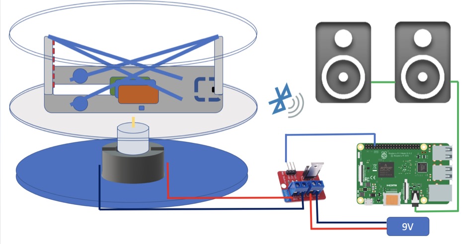
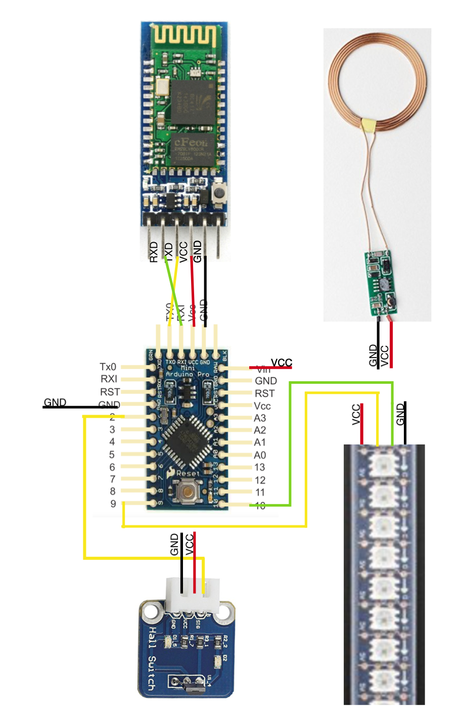
Figure 1: the hardware design
Hardware Design
The Propeller Displayer
The propeller clock module, the primary display screen of the system, is consisted of the following main hardware components:
1. A 12V motor, which is attached under the base board and fixed by a motor holder to the base board, is utilized to rotate the proto board.
2. Here the proto board is a PCB board that is used to hold the other major components, including the Adafruit Dotstar LED strip, the Arduino Pro mini, the Hall sensor, and the Bluetooth to UART module.As for these components on the protoboard, a Dotstar LED strip with 8 LEDs will be used to display the content while rotating.
3. Arduino pro mini will be used to control the LED strip display and communicate with the Raspberry Pi3 to control the whole system.
4. A wireless Bluetooth to UART converter will be used to transmit the control signal from Raspberry Pi 3 to Arduino.
5. A hall sensor, which is fixed on the board, together with a magnet, which is fixed on the regular mirror surface, is used to detect the starting point and refresh the display screen.
6. A DC motor control module is planned to be connected with the board and control the rotating speed of the board( which was removed in the end as it introduced unstability to the motor rotating speed). In this module, balancing of the propeller clock will be our major challenge.
7. The primary power supply of the propeller displayer module is achieved with the help of a 12V 600mA wireless charging module. Three main power supply techniques were tried out thoroughly (explained in the next part), we choose the inductive charging system due to its lightweight and space-saving features.
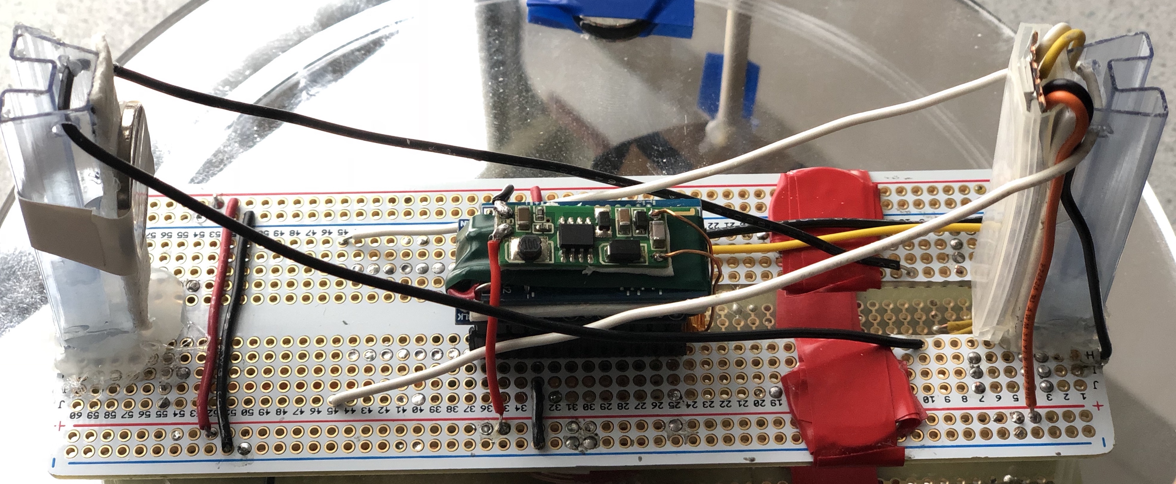
Figure 2: the protoboard
The Infinity Mirror
The infinity mirror adds a bonus mesmerizing visual effect for the whoe system. This module contains a special one-way mirror, a regular mirror, and a baseboard. All mirrors will be laser cut to be round-shaped. The special top mirror (the one-way mirror) is 50% reflective and 50% transmissive; the mirror in the middle (under the rotating board and on top of the 12V motor of the propeller clock) is a normal mirror that reflects the light. The normal mirror is used to reflect the LED screen display and will be installed in between the rotating board and the 12V motor. The displayed message will bounce back and forth between the two mirrors. With some lights escaping from the top mirror, the reflected displaying will become less and less each time. In this way, the gradually dimming illusion can be observed as hundreds of depths.
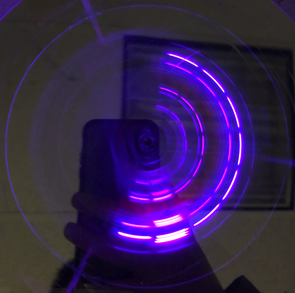
Figure 3: the infinity mirror
The Raspberry Pi 3 Control Module
In order to control the display messages of the propeller displayer and achieve the automation of the whole system, Raspberry pi 3 is used to communicate with the propeller clock module.Raspberry Pi sends the commands to Arduino and the Arduino will control the LED strip to display the different patterns.
I used the socket library to transmit the messages between Raspberry Pi and Arduino. I designed a simple communication protocol between these two device which includes sending message, receiving message, cleaning the buffer and response to make sure the communication is robust.
For text display. The Arduino stored the char library. And it stores some defaults string. Arduino displays the texts according to the commands from Raspberry Pi.
For time display. The Raspberry will get the current time and send it to the Arduino. The Arduino will display the time. And raspberry pi will send the update signal to the Arduino to update the time.
For music spectrum display. Raspberry Pi will decode the music and generate the music spectrum. For each frame, raspberry Pi will send 8 number which means the magnitude of 8 different frequency range. Arduino receives the signal and update each frame. Because the baud rate restriction, we can only display some simple patterns. I will work on other communication
Software Design
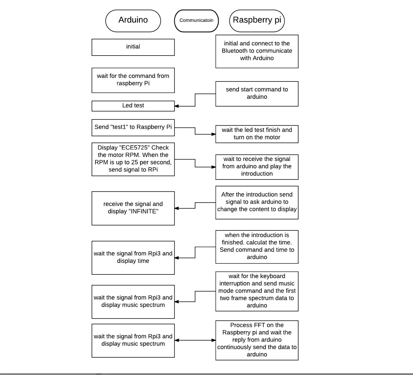
Figure 4: software design flow chart
Other hardware modules on the propeller displayer
- For the 12V rotating motor, we will solder the motor with proper wire first, then connect the motor with NRF520 MOS to control the rotating speed.
- For the motor holder, we plan to use Fusion 360 to design it and use 3D printing to print it from Cornell RPL lab.
- For the hall sensor, we will modify the structure of the hall sensor to be more friendly to be soldered on the prototype board. We will test the reading distance of the hall sensor (Expected to be about 1 cm).
- For the Dotstar LED strip, we plan to test and light the led strip using the strandtest program on Adafruit Dotstar website.
- For the rotating board, we will cut the Adafruit full size prototype board to fit the motor and let the LED light pass the creavice of the board to be reflected. All other components will be soldered on the board.
Testing & Redesign
Performance testing and Re-design
The test and redesign steps for the major components of the system were conducted as follows:
Propeller clock displayer balancing
The propeller displayer was the main display screen for the whole system. It utilizes persistence of vision theory to display the illusion of stable patterns floating in the air, thus it requires demanding rotation balance skills, which does not fall within our familiar expertise.
The protoboard system was even not balanced when we set up the initial system and began the rotation test. We first changed the Li-ion battery position as initially we put the battery on one side of the rotating board. As the battery is definitely the heaviest part on the board, we put it to the center hoping to improve. But as the battery module itself was not symmetric, we still cannot balance the system. We searched several solutions on Internet, and removed our power supply system for the propeller clock off-board (explained in power redesign module), then the board itself can be balanced.
Then the led strip was added, the rotating clock could not maintain balance again. One possible reason may be that the LED strip is too soft to keep in position when the motor was rotating at a high speed(around 1800 rpm). As for this factor, we thought of using structure wood to support the led strip. Another possible reason for the unbalance introduced by the led strip is that the LED strip was mounted only on one side, we need to add one similar structure to the other side to balance during rotating. In the end, we found a more stiff material to hold the LED strip and use four wires to hold the whole system, structured like a bridge. We also added some coins to balance the weight and adjust carefully the distance. Finally, the whole system was successfully balanced with all components.
Charging system re-design
The redesign of the charging system has gone through a Li-ion battery to a slip ring, then to inductive wireless charging module. At first, a rechargeable Li-ion battery will be used to charge the propeller clock module. Following our initial charging system design, we successfully recharge the Li-ion battery using the lab power supply equipment, and modified the Li-ion battery boost module, added a switch to control the power and added a charging circuit, in the end, we successfully have 5V output. But as the cumbersomeness of the battery made balancing rotating board so difficult, we removed it and tried slip ring to power the rotary part.
We made a slip ring to replace the Li-ion battery with the following steps:
- Cut copper and aluminum slice to make a metal roll.
- Cut the AA battery to get a perfect metal roll.
- Cut the copper to get a perfect electrode.
- Design its mechanical structure to make it more reliable.
- Testing its reliability on high speed.
The finished part picture is shown as below:
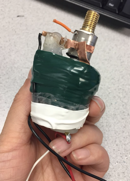
Figure 5: slip ring charging for propeller clock
The finished slip ring worked mostly OK except the motor became hot after some time when rotating. We suspect it’s mainly because of the insulation(the tape and glue) when fixing the slip ring on the motor. Also the slip ring will increase the resistance of the rotation part, thus the rotating board will become somewhat unstable.To combat this problem, we experimented inductive charging module to power the propeller displayer system, and tested the set with oscilloscope and assembled it on the system. This is a lightweight and stable solution that we finally choose to use for our project.
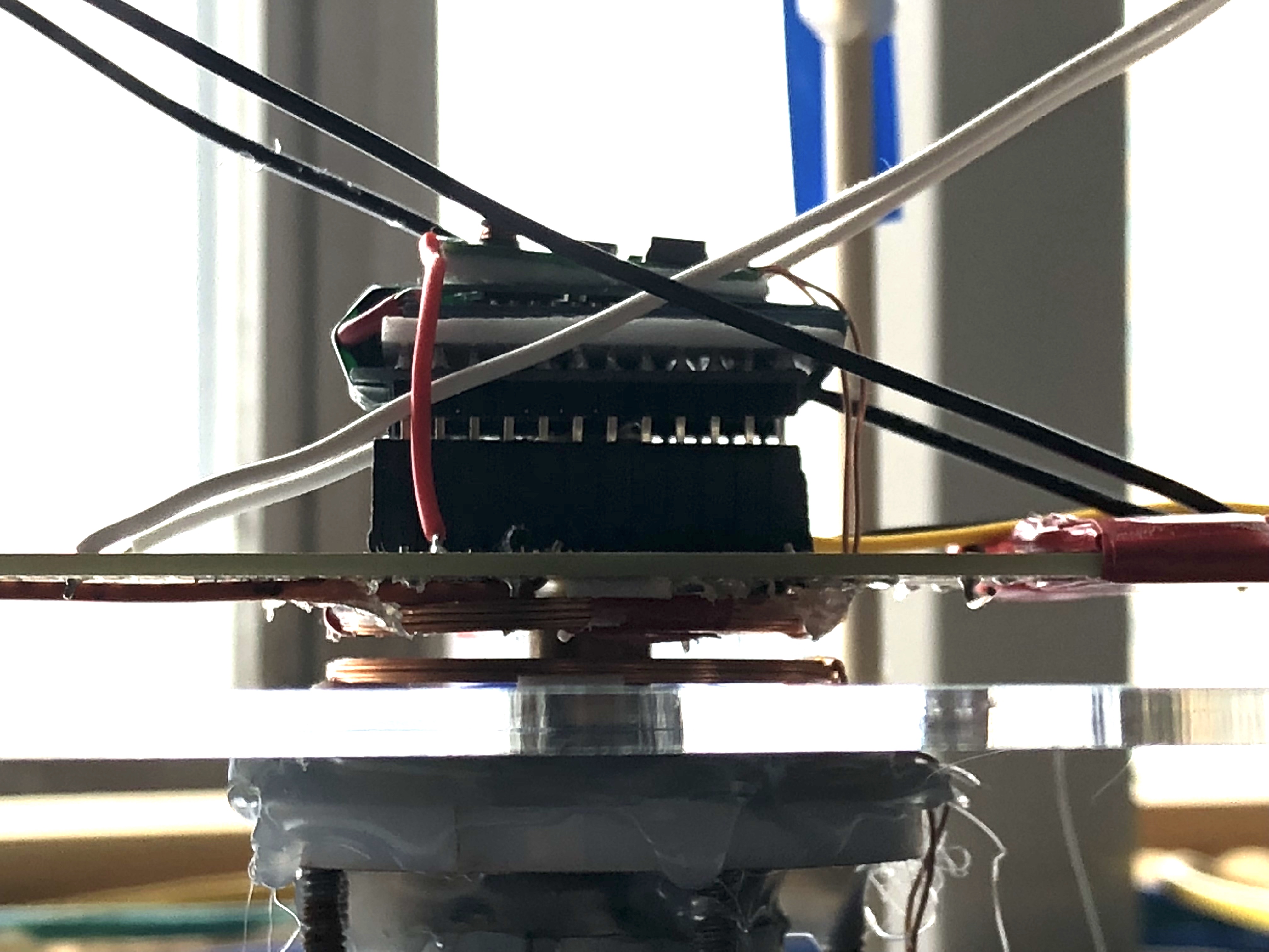
Figure 6: inductive charging module
Bluetooth to uart communication module design
The Bluetooth to UART communication module is an essential part of the system communication and controlling. We initially used the module HC-06 to test the communication between the two microcontrollers, but we cannot get the desired reply from the serial to the Raspberry Pi monitor. To debug, we first checked all the hardware and made sure that the circuit is correctly connected. Then, we checked the connection between our computer Bluetooth connection and the module. The HC-06 module could connect to the computer correctly. We then did research on the internet and found similar bugs related to the HC-06 module, so we switched to HC-05 module instead. Using HC-05 module, the testing program could be uploaded successfully. We were also able to achieve the bi-directional communication between Raspberry Pi 3 and Arduino pro mini: the command could be sent to Arduino from Raspberry Pi 3; Raspberry Pi 3 could receive and display the reply information from Arduino. Finally, we redesigned the connector between the Bluetooth module and the Arduino pro mini to make it more compact and easier to balance on the rotating board.
Display design
Initially when Raspberry Pi 3 communicated the with Arduino pro mini, the reply from the Arduino was not correct. After some research we figured out that a time lapse need to be added between sending the command and receiving the reply. Otherwise, the reply will not be prepared, then the receiving buffer would not have the full reply. That’s the reason that the reply displayed on the screen was not correct. Then, after figuring out the bugs, we see the result! Awesome!
At first, the character displaying effect on the propeller displayer is similar with the picture shown below(left): the shortest distance between the led light spot was separated around 4-5 centimeters. To improve the displaying effect, we reduced the delay time and finally delete the delay time between the two status(light on and off) entirely, but it didn’t work.
So, we suspected that the effect of the fastest updating rate may just be like this. We then searched the document of the dotstar led strip on internet and found that the updating rate could be super fast: for Arduino, the PWM rating could be 8MHZ, which is the clock rate. If that is true, we were supposed to get a better POV effect than the displayed effect. We then figured it might be the software problem. As we were using the Adafruit library previously, twe tried the Fastled library to see the display effect. It worked! The displaying effect with the new library is much better, shown in the picture below(middle).
With the new library, we could display the characters on screen better, but we want to display messages more precise and mimic the real-world display. So we tried to change the software SPI to hardware SPI by changing the connection within the system and got an even better display effect as shown in the picture below(right).
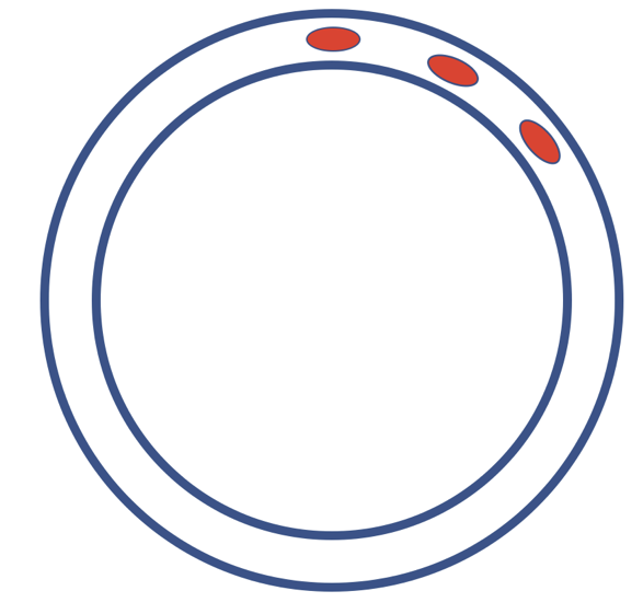
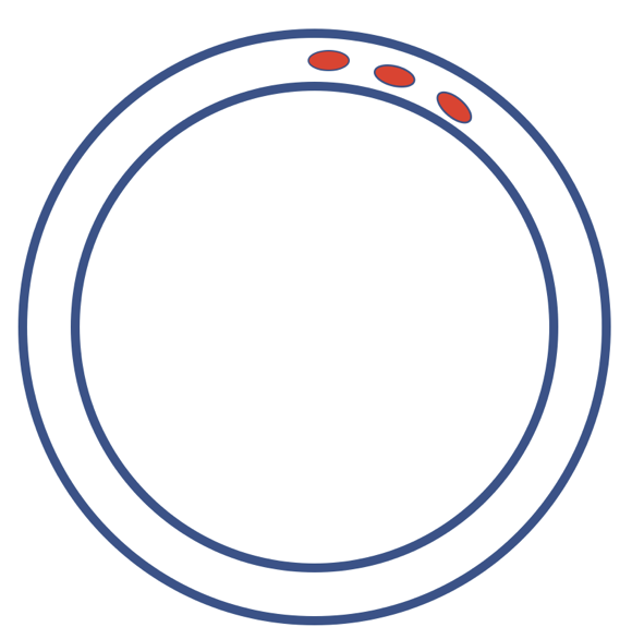
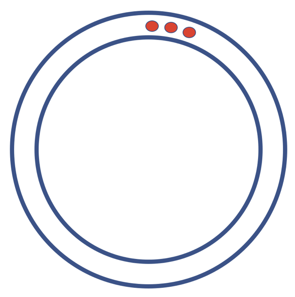
Figure 7: display optimization
Based on the third solution, we successfully displayed the character “ECE5725” on our system.
Result
The main objectives outlined in the initial project plan were achieved successfully. We have finished the propeller displaying function, the infinity mirror displaying part, the music spectrum displaying module, control function. The few bumps happened mainly when we tried to balance the whole system, trying out the charging systems, displaying music spectrums.
The Propeller Displayer: the rotating propeller clock requires state-of-art soldering, delicate assembly of all the components on a small board, creative balancing ideas, numerous testing, failures, and improvements along the way.
The Infinity Mirror: The optical effects of the infinity mirror, combined with the propeller clock display, is a unique display system originated from creativity and passion.
The Raspberry Pi 3 Control Module: the Raspberry Pi3 control program is versatile in that it can be expanded to include more display modes by just including the corresponding display messages and switching functions.
Conclusions
Overall, this project allowed us to devote time exploring a cool project that we felt would be expanded to a real stunning product in real lives.
Future work
For the future work of this project, we planed the below functions: the system can receive music signals from mobile phone, a special equipment to control the display depth of the infinity mirror can be designed, so that more display effect choices can be set. We also want to add more interactive functions to this displayer like a touch screen or voice control. All in all, in the end we want our product to achieve touch screen, voice control and displaying depth control functions. We will continue to finish all these functions after this course.
TEAM MEMBERS
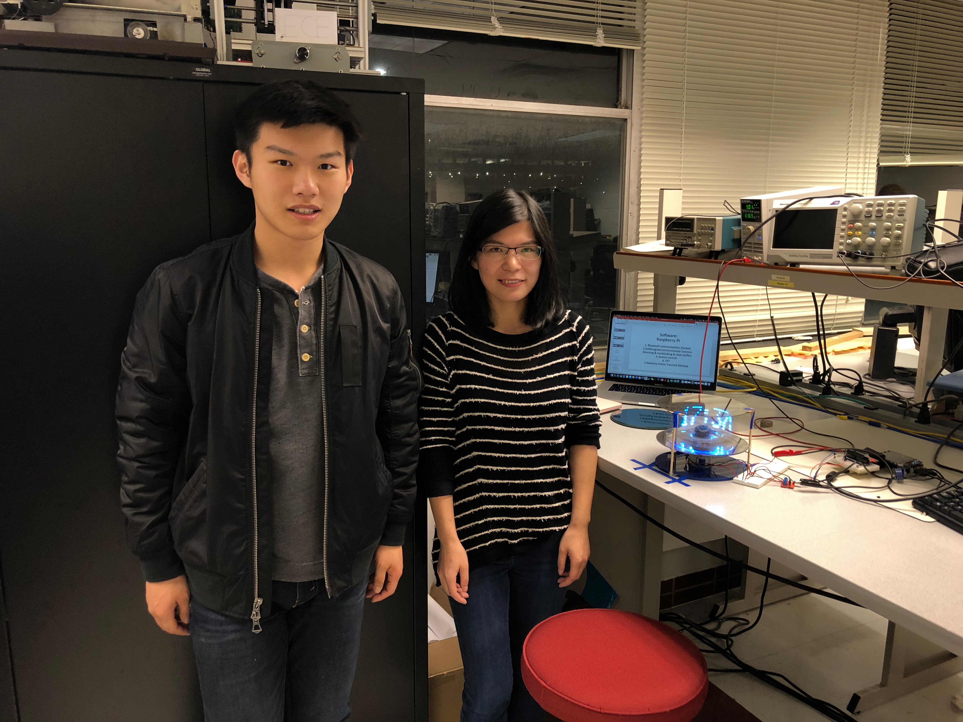
Group picture
In terms of the contributions, BeiTong focused on the hardware hacking and software design, while Qian focused on the software testing and the beginning of display program . We tested different techniques for balancing the system together, and BeiTong built the music spectrum display program part. This brilliant idea was brought up by Beitong Tian, and he contributed a lot of his prior expertise and experience on Embedded Operating Systems.
Materials and Costs
| Parts | Cost/Dollar | Source |
|---|---|---|
| Motor 12V with Copper head | 10 | Amazon |
| Bluetooth to Uart Converter | 7.5 | Amazon |
| Hall sensor | 5 | Amazon |
| Inductive Charging Module | 10 | Amazon |
| Raspberry Pi 3 | 35 | Provided in lab |
| Arduino pro mini | 6.5 | Provided in lab |
| One-way mirror | 15 | Amazon |
| Regular mirror | 9 | Amazon |
| Adafruit Dotstar LED strip | 5 | Amazon |
| Proto board | 0 | Provided in lab |
| Motor holder | 0 | 3D printed in RPL |
| Infinity mirror Base | 0 | Recycled |
| Total | 103 |
Code Appendix
1 2 3 4 5 6 7 8 9 10 11 12 13 14 15 16 17 18 19 20 21 22 23 24 25 26 27 28 29 30 31 32 33 34 35 36 37 38 39 40 41 42 43 44 45 46 47 48 49 50 51 52 53 54 55 56 57 58 59 60 61 62 63 64 65 66 67 68 69 70 71 72 73 74 75 76 77 78 79 80 81 82 83 84 85 86 87 88 89 90 91 92 93 94 95 96 97 98 99 100 101 102 103 104 105 106 107 108 109 110 111 112 113 114 115 116 117 118 119 120 121 122 123 124 125 126 127 128 129 130 131 132 133 134 135 136 137 138 139 140 141 142 143 144 145 146 147 148 149 150 151 152 153 154 155 156 157 158 159 160 161 162 163 164 165 166 167 168 169 170 171 172 173 174 175 176 177 178 179 180 181 182 183 184 185 186 187 188 189 190 191 192 193 194 195 196 197 198 199 200 201 202 203 204 205 206 207 208 209 210 211 212 213 214 215 216 217 218 219 220 221 222 223 224 225 226 227 228 229 230 231 232 233 234 235 236 237 238 239 240 241 242 243 244 245 246 247 248 249 250 251 252 253 254 255 256 257 258 259 260 261 262 263 264 265 266 267 268 269 270 271 272 273 274 275 276 277 278 279 280 281 282 283 284 285 286 287 288 289 290 291 292 293 294 295 296 297 298 299 300 301 302 303 304 305 306 307 308 309 310 311 312 313 314 315 316 317 318 319 320 321 322 323 324 325 326 327 328 329 330 331 332 333 334 335 336 337 338 339 340 341 342 343 344 345 346 347 348 349 350 351 352 353 354 355 356 357 358 359 360 361 362 363 364 365 366 367 368 369 370 371 372 373 374 375 376 377 378 379 380 381 382 383 384 385 386 387 388 389 390 391 392 393 394 395 396 397 398 399 400 401 402 403 404 405 406 407 408 409 410 411 412 413 414 415 416 417 418 419 420 421 422 423 424 425 426 427 428 429 430 431 432 433 434 435 436 437 438 439 440 441 442 443 444 445 446 447 448 449 450 451 452 453 454 455 456 457 458 459 460 461 462 463 464 465 466 467 468 469 470 471 472 473 474 475 476 477 478 479 480 481 482 |
// web_version.ino #include <FastLED.h> #define NUM_LEDS 8 CRGB leds[NUM_LEDS]; // FastLED library data structure //functions void rpm_cal(); void printLetter(char ch); void display_test(int times); void printLetter(char ch, long interval); void printLetter_new(char ch, int interval,long color); void show_frame(int content, int total_number,long color) ; void show_sigleunit(long color,byte b, int width_color, int width_black ) ; void show_singleline(long color, byte b); void time_converter(int hour, int mini, int second); void speed_control(); void parse_command(); void parse_print(); void led_test1(); void clean_buffer(); //variables int rate =4; int circle_count = 0; int str_len = 0; int black_len = 0; volatile int count =0; int update_frame = 0; int rows= 8; const int charHeight = 8; const int charWidth = 5; long time_his = 0; long time_his2 = 0; byte check = 0; long timeinterval =0; bool error = 0; bool music_mode = 0; bool music_update_frame =1; char music_his[8] = {0xFE,0xFE,0xFE,0xFE,0xFE,0xFE,0xFE,0xFE}; long color_select = 0xFF0000; int rpm =0; int time_pins = 0; long lastmillis = 0; int k = 0; String btdata = "String"; int test2pass = 0; String trash = ""; bool speedtest = 0; int print_mode = 1; int music = 0; bool time_start = 0; int hour = 0; int mini= 0; int second = 0; String H = "0"; String M = "0"; String S = "0"; bool time_update_frame = 0; const unsigned char font[95][5] = { {0x00,0x00,0x00,0x00,0x00}, // 0x20 32 {0x00,0x00,0x6f,0x00,0x00}, // ! 0x21 33 {0x00,0x07,0x00,0x07,0x00}, // " 0x22 34 {0x14,0x7f,0x14,0x7f,0x14}, // # 0x23 35 {0x00,0x07,0x04,0x1e,0x00}, // $ 0x24 36 {0x23,0x13,0x08,0x64,0x62}, // % 0x25 37 {0x36,0x49,0x56,0x20,0x50}, // & 0x26 38 {0x00,0x00,0x07,0x00,0x00}, // ' 0x27 39 {0x00,0x1c,0x22,0x41,0x00}, // ( 0x28 40 {0x00,0x41,0x22,0x1c,0x00}, // ) 0x29 41 {0x14,0x08,0x3e,0x08,0x14}, // * 0x2a 42 {0x08,0x08,0x3e,0x08,0x08}, // + 0x2b 43 {0x00,0x50,0x30,0x00,0x00}, // , 0x2c 44 {0x08,0x08,0x08,0x08,0x08}, // - 0x2d 45 {0x00,0x60,0x60,0x00,0x00}, // . 0x2e 46 {0x20,0x10,0x08,0x04,0x02}, // / 0x2f 47 {0x3e,0x51,0x49,0x45,0x3e}, // 0 0x30 48 {0x00,0x42,0x7f,0x40,0x00}, // 1 0x31 49 {0x42,0x61,0x51,0x49,0x46}, // 2 0x32 50 {0x21,0x41,0x45,0x4b,0x31}, // 3 0x33 51 {0x18,0x14,0x12,0x7f,0x10}, // 4 0x34 52 {0x27,0x45,0x45,0x45,0x39}, // 5 0x35 53 {0x3c,0x4a,0x49,0x49,0x30}, // 6 0x36 54 {0x01,0x71,0x09,0x05,0x03}, // 7 0x37 55 {0x36,0x49,0x49,0x49,0x36}, // 8 0x38 56 {0x06,0x49,0x49,0x29,0x1e}, // 9 0x39 57 {0x00,0x36,0x36,0x00,0x00}, // : 0x3a 58 {0x00,0x56,0x36,0x00,0x00}, // ; 0x3b 59 {0x08,0x14,0x22,0x41,0x00}, // < 0x3c 60 {0x14,0x14,0x14,0x14,0x14}, // = 0x3d 61 {0x00,0x41,0x22,0x14,0x08}, // > 0x3e 62 {0x02,0x01,0x51,0x09,0x06}, // ? 0x3f 63 {0x3e,0x41,0x5d,0x49,0x4e}, // @ 0x40 64 {0x7e,0x09,0x09,0x09,0x7e}, // A 0x41 65 {0x7f,0x49,0x49,0x49,0x36}, // B 0x42 66 {0x3e,0x41,0x41,0x41,0x22}, // C 0x43 67 {0x7f,0x41,0x41,0x41,0x3e}, // D 0x44 68 {0x7f,0x49,0x49,0x49,0x41}, // E 0x45 69 {0x7f,0x09,0x09,0x09,0x01}, // F 0x46 70 {0x3e,0x41,0x49,0x49,0x7a}, // G 0x47 71 {0x7f,0x08,0x08,0x08,0x7f}, // H 0x48 72 {0x00,0x41,0x7f,0x41,0x00}, // I 0x49 73 {0x20,0x40,0x41,0x3f,0x01}, // J 0x4a 74 {0x7f,0x08,0x14,0x22,0x41}, // K 0x4b 75 {0x7f,0x40,0x40,0x40,0x40}, // L 0x4c 76 {0x7f,0x02,0x0c,0x02,0x7f}, // M 0x4d 77 {0x7f,0x04,0x08,0x10,0x7f}, // N 0x4e 78 {0x3e,0x41,0x41,0x41,0x3e}, // O 0x4f 79 {0x7f,0x09,0x09,0x09,0x06}, // P 0x50 80 {0x3e,0x41,0x51,0x21,0x5e}, // Q 0x51 81 {0x7f,0x09,0x19,0x29,0x46}, // R 0x52 82 {0x46,0x49,0x49,0x49,0x31}, // S 0x53 83 {0x01,0x01,0x7f,0x01,0x01}, // T 0x54 84 {0x3f,0x40,0x40,0x40,0x3f}, // U 0x55 85 {0x0f,0x30,0x40,0x30,0x0f}, // V 0x56 86 {0x3f,0x40,0x30,0x40,0x3f}, // W 0x57 87 {0x63,0x14,0x08,0x14,0x63}, // X 0x58 88 {0x07,0x08,0x70,0x08,0x07}, // Y 0x59 89 {0x61,0x51,0x49,0x45,0x43}, // Z 0x5a 90 {0x3c,0x4a,0x49,0x29,0x1e}, // [ 0x5b 91 {0x02,0x04,0x08,0x10,0x20}, // \ 0x5c 92 {0x00,0x41,0x7f,0x00,0x00}, // ] 0x5d 93 {0x04,0x02,0x01,0x02,0x04}, // ^ 0x5e 94 {0x40,0x40,0x40,0x40,0x40}, // _ 0x5f 95 {0x00,0x00,0x03,0x04,0x00}, // ` 0x60 96 {0x20,0x54,0x54,0x54,0x78}, // a 0x61 97 {0x7f,0x48,0x44,0x44,0x38}, // b 0x62 98 {0x38,0x44,0x44,0x44,0x20}, // c 0x63 99 {0x38,0x44,0x44,0x48,0x7f}, // d 0x64 100 {0x38,0x54,0x54,0x54,0x18}, // e 0x65 101 {0x08,0x7e,0x09,0x01,0x02}, // f 0x66 102 {0x0c,0x52,0x52,0x52,0x3e}, // g 0x67 103 {0x7f,0x08,0x04,0x04,0x78}, // h 0x68 104 {0x00,0x44,0x7d,0x40,0x00}, // i 0x69 105 {0x20,0x40,0x44,0x3d,0x00}, // j 0x6a 106 {0x00,0x7f,0x10,0x28,0x44}, // k 0x6b 107 {0x00,0x41,0x7f,0x40,0x00}, // l 0x6c 108 {0x7c,0x04,0x18,0x04,0x78}, // m 0x6d 109 {0x7c,0x08,0x04,0x04,0x78}, // n 0x6e 110 {0x38,0x44,0x44,0x44,0x38}, // o 0x6f 111 {0x7c,0x14,0x14,0x14,0x08}, // p 0x70 112 {0x08,0x14,0x14,0x18,0x7c}, // q 0x71 113 {0x7c,0x08,0x04,0x04,0x08}, // r 0x72 114 {0x48,0x54,0x54,0x54,0x20}, // s 0x73 115 {0x04,0x3f,0x44,0x40,0x20}, // t 0x74 116 {0x3c,0x40,0x40,0x20,0x7c}, // u 0x75 117 {0x1c,0x20,0x40,0x20,0x1c}, // v 0x76 118 {0x3c,0x40,0x30,0x40,0x3c}, // w 0x77 119 {0x44,0x28,0x10,0x28,0x44}, // x 0x78 120 {0x0c,0x50,0x50,0x50,0x3c}, // y 0x79 121 {0x44,0x64,0x54,0x4c,0x44}, // z 0x7a 122 {0x00,0x08,0x36,0x41,0x41}, // { 0x7b 123 {0x00,0x00,0x7f,0x00,0x00}, // | 0x7c 124 {0x41,0x41,0x36,0x08,0x00}, // } 0x7d 125 {0x04,0x02,0x04,0x08,0x04}, // ~ 0x7e 126 }; String string2show = "ECE5725"; void setup() { FastLED.addLeds<APA102>(leds, NUM_LEDS); // setup the led strip using fast-led lib Serial.begin(57600); // set the serial baud rate 57600 is the download rate of arduino. So we can wirelessly upload. attachInterrupt(digitalPinToInterrupt(2), rpm_cal, FALLING); // setup the external interrupt // now it is the start mode code sectoin in arduino clean_buffer(); // clean the buffer while (Serial.available() == 0) {} //wait until there are some information come in delay(100); // wait to receive the whole data btdata = Serial.readString(); //read the data and store the data in btdata if(btdata == "1") led_test1(); //actually there will not be orther command here is just to show it can receive the right data. So actually it is a debug point //execute the led test program Serial.println("test1"); //send back the respond to raspberry pi } void loop() { if(update_frame == 1 ) { update_frame = 0; if(print_mode == 4) { circle_count = circle_count + 1; show_frame(2,100,0xFF00FF); if (circle_count == rate) { //updafe spectrum every (rate) circles music_update_frame = 1; //allow to update music spectrum frame Serial.println("go"); //send signal to Rp3 to send new data to buffer circle_count = 0; } } else show_frame(1, 100, color_select); //show text when the print_mode is not 4 //speed control //update_frame the rpm and trasmit the signal to raspberry pi. //When the spped is up to 25 rpm. It will send a signal to raspberry pi to tell the motor starts correctly if (millis() - lastmillis >= 1000 &&speedtest == 0){ speed_control(); } //receive the command and stop receiving command in music mode if (Serial.available() && music_mode == 0) { parse_command(); } //change the print text according to the display mode when it is not in music mode if(print_mode != 4) parse_print(); } } //interrupt funtion enter this function every circle void rpm_cal() { time_pins ++; update_frame = 1; } //this is a test fuction. It will display on - off loop for x times void display_test(int times){ for (int i = 0 ; i< times ; i++) { for (int j = 0; j < 8; j ++) { leds[j] = CRGB::Red; } FastLED.show(); for (int j = 0; j < 8; j ++) { leds[j] = CRGB::Black; } FastLED.show(); } } //This is the initial led test program. All 8 leds will show red, green and blue void led_test1() { for (int i=0; i<8; i++) { leds[i] = CRGB::Blue; } FastLED.show(); delay(1000); for (int i=0; i<8; i++) { leds[i] = CRGB::Green; } FastLED.show(); delay(1000); for (int i=0; i<8; i++) { leds[i] = CRGB::Red; } FastLED.show(); delay(1000); for (int i=0; i<8; i++) { leds[i] = CRGB::Black; } FastLED.show(); } //this is the function to print single letter //ch is the character index which is corresponded to the char list //interval is the interval between each letter //color is the color to display this letter which is 24 bit Ex. 0xFF0000 is red void printLetter_new(char ch, int interval,long color,int interval_unit) { if (ch < 32 || ch > 126){ ch = 32; } ch -= 32; for (int i=charWidth-1; i>-1; i--) { byte b = font[ch][i]; if(i != 0) show_sigleunit(color,b,1,interval_unit); else if( i == 0 && k != 0) show_sigleunit(color,b,1,interval_unit+interval); else if( i == 0 && k == 0) show_sigleunit(color,b,1,interval_unit); } } //This is the frame update function //content is the mode number //1 is to show letter //2 is to show music spectrum void show_frame(int content, int total_number,long color) { if(content == 1) { str_len = string2show.length(); black_len = (total_number - str_len*5 - (str_len-1)*3)/2; show_sigleunit(0x00000,0xFF,black_len,0); for(k = string2show.length(); k>-1; k--) printLetter_new(string2show.charAt(k),1,color,1); } if(content == 2){ show_sigleunit(0x00000,0xFF,40,0); if (music_update_frame == 1){ //when the frame is updated, read data from buffer and display for(int m = 0; m< 8; m++) { music = Serial.read(); music_his[m] = (0xFF<< (56-music)); show_sigleunit(color, music_his[m], 8, 2); music_update_frame = 0; } } else if(music_update_frame == 0) { //when the frame is not updated, read data from buffer history for(int m = 0; m< 8; m++) { show_sigleunit(color, music_his[m], 8, 2); } } } } //This function is to show single unit. //A unit is a combination of showing single-line //color is the 24 bit color //b is the code to display //width_color is the led length we want to display //width_black is the black length we want to display void show_sigleunit(long color,byte b, int width_color, int width_black ) { for (int i = 0 ; i<width_color ; i++) show_singleline(color,b); for (int i = 0 ; i<width_black ; i++) show_singleline(0x000000,0xFF); } //This is the function to show the single line void show_singleline(long color, byte b){ for (int i=0; i<8; i++) { if (bitRead(b,i)) leds[i] = color; else leds[i] = 0x000000; } FastLED.show(); } //this fucniton is to convert the time to the right format to display void time_converter(int hour, int mini, int second) { if (hour<10) { H = hour; H = "0" + H;} else H = hour; if (mini < 10) { M = mini; M = "0" + M;} else M = mini; if (second < 10) { S = second; S = "0" + S;} else S = second; string2show = H + ":" + M + ":" + S ; } //This function is to parse the print content void parse_print() { if(print_mode == 1) { string2show = "ECE5725"; color_select = 0xFF0000; } else if (print_mode == 2){ string2show = "INFINITE"; color_select = 0xFFF000; } else if (print_mode == 3) { if (time_update_frame == 1) { time_update_frame = 0; second = second + 1; if (second >= 60) { mini = mini + 1; second = 0; } if (mini >= 60 ) { hour = hour + 1; mini = 0; } if (hour == 24){ hour = 1; } time_converter(hour,mini,second); } } else string2show = btdata; } //This is the speed calculation function void speed_control(){ detachInterrupt(0);//Disable interrupt when calculating rpm = time_pins; // Convert frecuency to RPM, note: this works for one interruption per full rotation. For two interrups per full rotation use time_pins * 30. if(rpm >= 25 && speedtest == 0) { Serial.println("test2"); // print the rpm value. speedtest = 1; } time_pins = 0; // Restart the RPM counter lastmillis = millis(); // Uptade lasmillis attachInterrupt(0, rpm_cal, FALLING); //enable interrupt } //This is the command parse function. //It will read in the command and then parse it to different display mode void parse_command() { btdata = Serial.read(); //read String is very slow so we should use read byte if(btdata == "50") { print_mode = 2; time_start = 0; clean_buffer(); } else if(btdata == "51" ) { if (time_start == 0) { hour = ((Serial.read()-48)*10 + Serial.read()-48); mini = ((Serial.read()-48)*10 + Serial.read()-48); second = ((Serial.read()-48)*10 + Serial.read()-48); time_converter(hour,mini,second); print_mode = 3; time_start = 1; } else{ print_mode = 3; time_update_frame = 1; } clean_buffer(); } else if(btdata == "52") { //music mode print_mode = 4; time_start = 0; music_mode = 1; } else { print_mode = 5; time_start = 0; clean_buffer(); } } //This is the clean buffer function which is to clean the serial buffer void clean_buffer() { //second version which is faster while (Serial.available()) { trash = Serial.read(); } } |
1 2 3 4 5 6 7 8 9 10 11 12 13 14 15 16 17 18 19 20 21 22 23 24 25 26 27 28 29 30 31 32 33 34 35 36 37 38 39 40 41 42 43 44 45 46 47 48 49 50 51 52 53 54 55 56 57 58 59 60 61 62 63 64 65 66 67 68 69 70 71 72 73 74 75 76 77 78 79 80 81 82 83 84 85 86 87 88 89 90 91 92 93 94 95 96 97 98 99 100 101 102 103 104 105 106 107 108 109 110 111 112 113 114 115 116 117 118 119 120 121 122 123 124 125 126 127 128 129 130 131 132 133 134 135 136 137 138 139 140 141 142 143 144 145 146 147 148 149 150 151 152 153 154 155 156 157 158 159 160 161 162 163 164 165 166 167 168 169 170 171 172 173 174 175 176 177 178 179 180 181 182 183 184 185 186 187 188 189 190 191 192 193 194 195 196 197 198 199 200 201 202 203 204 205 206 207 208 209 210 211 212 213 214 215 216 217 218 219 220 221 222 223 224 225 226 227 228 229 230 231 232 233 234 235 236 237 238 239 240 241 242 243 244 245 246 247 248 |
import socket import time import RPi.GPIO as GPIO import os import datetime import alsaaudio as aa import wave from struct import unpack import numpy as np # some variables for FFT spectrum = [1,1,1,3,3,3,2,2] matrix = [0,0,0,0,0,0,0,0] result = "" result_often = "" power= [] weighting = [2,8,8,16,16,32,32,64] music_frame = 1 # launch the music we will do the fft process wavfile = wave.open('/home/pi/project/abc.wav','r') sample_rate = wavfile.getframerate() no_channels = wavfile.getnchannels() chunk = 1024 # output the music after the FFT output = aa.PCM(aa.PCM_PLAYBACK,aa.PCM_NORMAL) output.setchannels(no_channels) output.setrate(sample_rate) output.setformat(aa.PCM_FORMAT_S16_LE) output.setperiodsize(chunk) def piff(val): return int(2*chunk*val/sample_rate) def calculate_levels(data, chunk,sample_rate): global matrix global result # Convert raw data (ASCII string) to numpy array data = unpack("%dh"%(len(data)/2),data) data = np.array(data, dtype='h') # Apply FFT - real data fourier=np.fft.rfft(data) # Remove last element in array to make it the same size as chunk fourier=np.delete(fourier,len(fourier)-1) # Find average 'amplitude' for specific frequency ranges in Hz power = np.abs(fourier) matrix[0]= int(np.mean(power[piff(0) :piff(156):1])) matrix[1]= int(np.mean(power[piff(156) :piff(313):1])) matrix[2]= int(np.mean(power[piff(313) :piff(625):1])) matrix[3]= int(np.mean(power[piff(625) :piff(1250):1])) matrix[4]= int(np.mean(power[piff(1250) :piff(2500):1])) matrix[5]= int(np.mean(power[piff(2500) :piff(5000):1])) matrix[6]= int(np.mean(power[piff(5000) :piff(10000):1])) matrix[7]= int(np.mean(power[piff(10000):piff(20000):1])) print "ori" print matrix # Tidy up column values for the LED matrix matrix=np.divide(np.multiply(matrix,weighting),1000000) print "tidy up" print matrix # Set floor at 0 and ceiling at 8 for LED matrix matrix=matrix.clip(1,8) print "floor" print matrix for t in range(0,7): result = result + str(matrix[t]) return result # BLUETOOTH connection with socket library bd_addr = "98:D3:31:40:08:51" #the address from the Arduino sensor port = 1 connected = 0 frame_rate = 1 rate = 20 frame =1 sock = socket.socket (socket.AF_BLUETOOTH,socket.SOCK_STREAM, socket.BTPROTO_RFCOMM) sock.connect((bd_addr,port)) # some bluetooth variables data = "" data_result ="" rpm = 0 trash = "" # set GPIO 4 to conntrol the motor GPIO.setmode(GPIO.BCM) GPIO.setup(4, GPIO.OUT, initial=GPIO.LOW) # readdata from bluetooth with blocking def readdata(length): length = length + 1 global data global data_result data_len = 0 temp = "" while not '\r' in data: # so there are still some data in the buffer temp= sock.recv(max(length-data_len,1)) data= data + temp data_len= data_len + len(temp) data_result = data.replace('\r', '') data_result = data_result.replace('\n', '') data = "" # read data from bluetooth with non-blocking def readdatanew(length): sock.settimeout(0) try: length = length + 1 global data global data_result data_len = 0 temp = "" temp= sock.recv(max(length-data_len,1)) data= data + temp data_len= data_len + len(temp) while not '\r' in data: # so there are still some data in the buffer temp= sock.recv(max(length-data_len,1)) data= data + temp data_len= data_len + len(temp) data_result = data.replace('\r', '') data_result = data_result.replace('\n', '') data = "" sock.settimeout(None) return data_result except: sock.settimeout(None) # empty the socket buffer def emptysocket(): sock.settimeout(0) try: trash = sock.recv(1024) print "trash is " print trash print "end" sock.settimeout(None) except : print "no data in the buffer" sock.settimeout(None) try: time.sleep(3) emptysocket() # wake up arduino time.sleep(3) sock.send("1") print "finish" # receive the speed data from arduino if the test program is finished turn on the motor readdata(5) emptysocket() print data_result if data_result == 'test1': GPIO.output(4,True) # receive the speed data from arduino if the speed is up to 25 which means the motor speed is relative stable # play the audio readdata(6) print data_result if data_result == "test2": print "you are fast enough" os.system('omxplayer /home/pi/project/start.wav&') time.sleep(10) emptysocket() # after 10s send the signal to arduino to change the string to display sock.send("2") os.system('omxplayer /home/pi/project/start2.wav&') time.sleep(48) # receive the signal and hour = datetime.datetime.now().strftime("%H") miniute = datetime.datetime.now().strftime("%M") second = datetime.datetime.now().strftime("%S") sock.send("3" + hour + miniute + second) second_history = second # Check the second. If the second changes, send a signal to arduino to update the time while 1: second = datetime.datetime.now().strftime("%S") print "now" print second print "history" print second_history if second_history != second: second_history = second print "come in" sock.send("3") # use control+c to switch to music mode except KeyboardInterrupt: print "clean" emptysocket() try: # read in the data mdata = wavfile.readframes(chunk) os.system('omxplayer /home/pi/project/abc.wav&') while mdata!='': # play the music output.write(mdata) if music_frame ==1: # process FFT on the data result_often = calculate_levels(mdata, chunk,sample_rate) print result_often sock.send("4" + "11111111" + result_often) result = "" music_frame = 0 # send new data to arduino if receive the signal elif (readdatanew(2) == "go"): result_often = calculate_levels(mdata, chunk,sample_rate) print result_often sock.send(result_often) result = "" mdata = wavfile.readframes(chunk) # clean all the stuff print "clean" emptysocket() GPIO.output(4,False) GPIO.cleanup() exit(0) # clean all the stuff except KeyboardInterrupt: print "clean" emptysocket() GPIO.output(4,False) GPIO.cleanup() exit(0) |