National Electrical Contest
More contents will be added soon~
National Electrical Contest is the largest electrical contest around Chinese undergraduate students. It is held by Ministry of Education and Ministry of Industry and Information Technology and sponsered by Texas Instruments at province level and by Renesas Electronics at national level. In 2015, there are 36378 students around the country took part in the contest. It is the biggest electrical engineer party in China.
My project is related to power. We built the digital control dc power supply, switching power supply modules parallel power supply system, single phase AC-DC converter circuit and active power factor correction in our summer training. And for the contest, we built bidirectional DC-DC converter for lithium battery in only 3 days and won the national first prize.
Demonstration Video(This video is our final contest project. We built a bidirectional DC-DC converter for lithium battery.)
Introduction
The design is by the boost module, constant current modules, digital modules and other components of high-efficiency two-way DC-DC circuit. Charging using high-efficiency buck chip TPS54340, added to the current loop, the current can be set, the current control accuracy of 0.13%, the current rate of change of 0.05%, the efficiency of 95.4%. Discharge TPS55340 form boost boost circuit, the output voltage is stable, the efficiency of 95.0%. The digital processing module of the system adopts STM32 one-chip computer with high processing speed and low power consumption to realize high-precision constant current charging and constant voltage discharge. It has the functions of overcharge protection, full charge, anti-reflux and battery residual judgment. System components, cost-effective, small size, light weight (250g), a better completion of the basic part and to play part of the requirements there is a certain degree of innovation. In addition, the design uses high-precision thermal transfer PCB board production, the basic all-chip process is conducive to the stable operation of high-frequency switching circuit.
Design
This the STM32F103 control board I designed for our team.

Figure 1: schematic of the control board
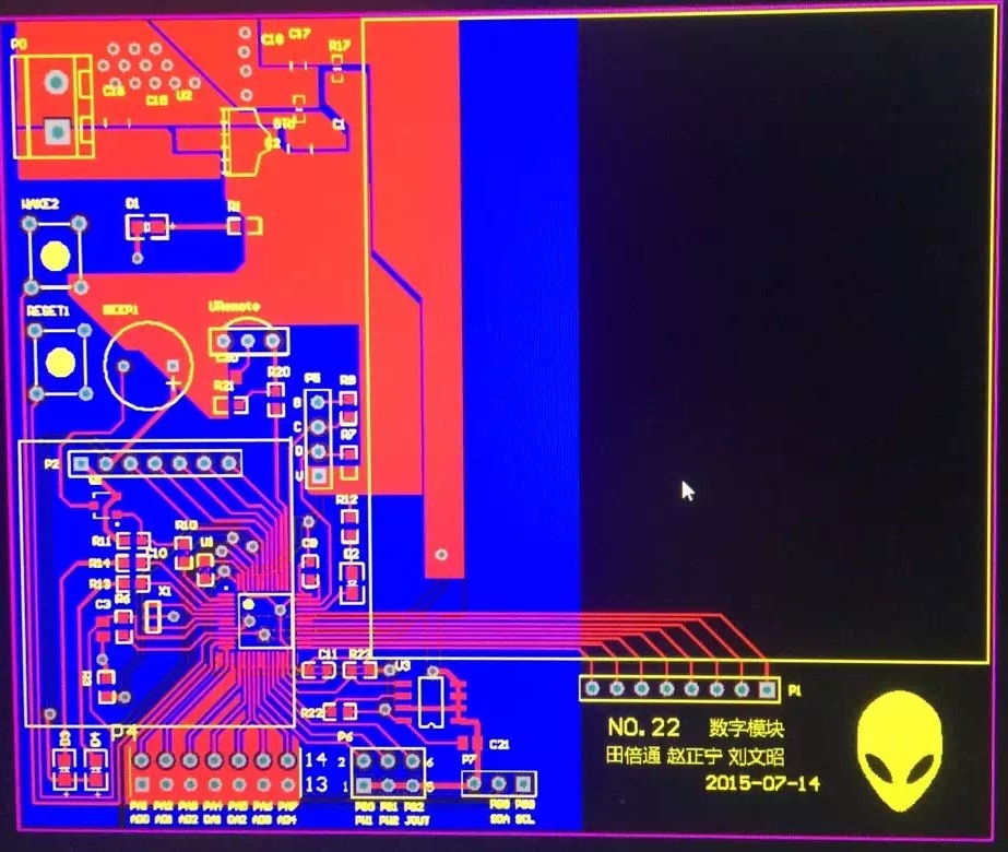
I used AltiumDesigner to design the board and make it to a PCB design.

Figure 2: PCB design
I soldered this board and debugged all the modules on the board like the oled screen, keyboard, ADC and DAC etc.
Figure 3: Finished Control Board
digital control dc power supply
Figure 4: digital control dc power supply
switching power supply modules parallel power supply system
Figure 5: switching power supply modules parallel power supply system
single phase AC-DC converter circuit and active power factor correction
Figure 6: single phase AC-DC converter circuit and active power factor correction
bidirectional DC-DC converter for lithium battery
Figure 7: bidirectional DC-DC converter for lithium battery

Figure 8: back of bidirectional DC-DC converter for lithium battery
Figure 9: all the boards we used during this contest
Team Member

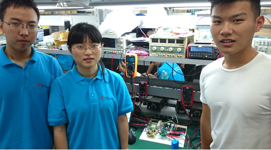
Figure 10: Zhengning Zhao, Wenzhao Liu, Beitong Tian(From left to right)